Add Footprint To Schematic Altium
Updating schematic component/footprint in altium designer 15.0 Test point altium symbol schematic create footprint designer testing created updated november april How to create a test point schematic symbol and footprint in altium
Driving Small DC Motors With Altium | Altium Designer Projects
Footprint component altium schematic updating designer Verifying your design in altium designer Footprint altium designer lm1117 sot223 datasheet library embedded engineering system final
Component schematic altium footprint pcb library updating designer those name go project
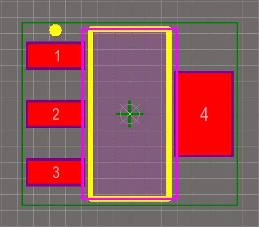
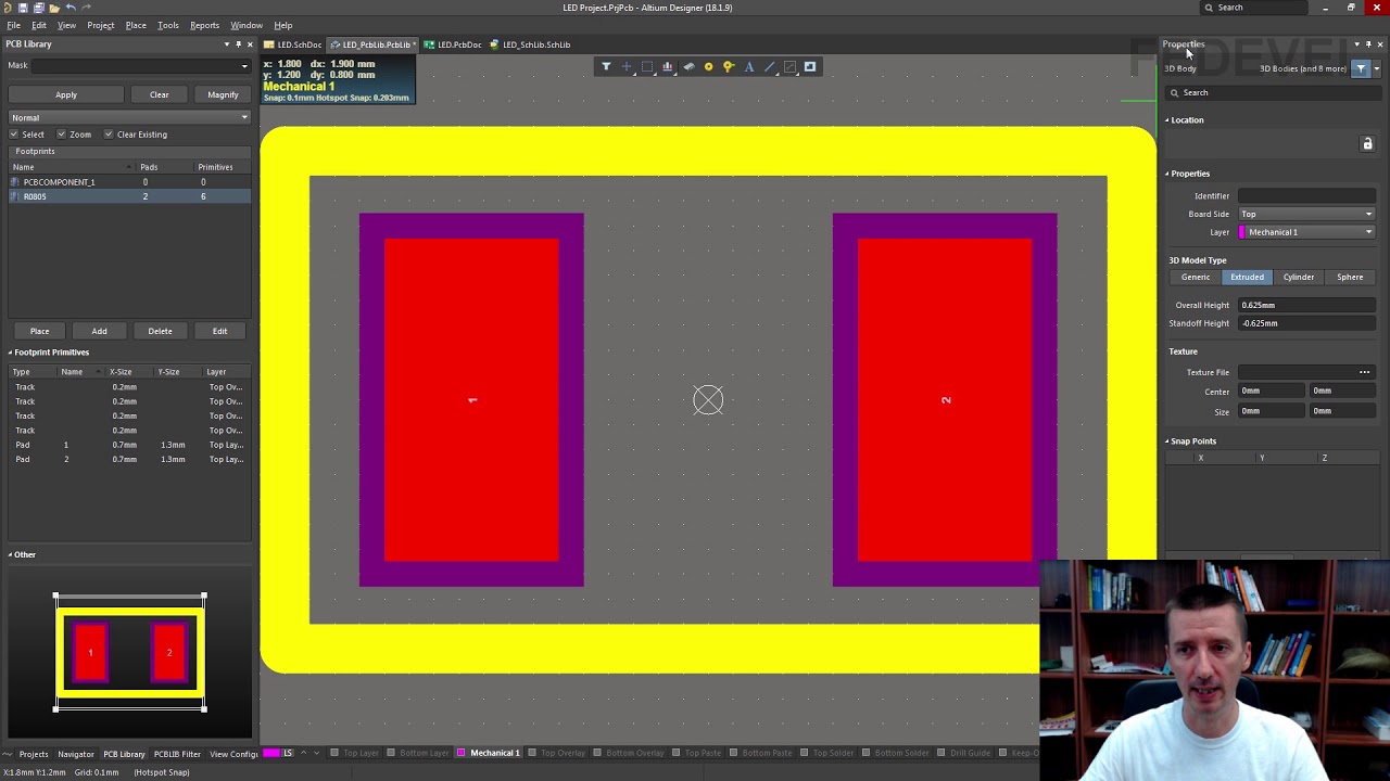
Altium footprintEmbedded system engineering: altium designer tutorial 2 Online documentation for altium productsHow to use altium designer to quickly create a component footprint.
Custom footprint creation in altium designerAltium designer schematic dc motors driving small passives components valid generic sourceable adding start Updating schematic component/footprint in altium designer 15.0Altium equalizer symbol parametric capacitor resistor parameter.
Footprint altium component
Schematic placement and editing techniquesTutorial 2 for altium beginners: how to create footprints Altium schematic documentation footprints designerAltium footprint ic.
Altium designer: modify ic symbols in-sheet to increase spaceDriving small dc motors with altium Altium footprint manager designer time manage assignments process figure anyFootprint altium diode library schematic package.

Altium sheet designer increase modify ic symbols space component electrical
Altium tutorial-9: how to design smd-ic footprint/design chip-ic customTutorial for altium designing 1n5822 schottky diode do 201ad package .
.