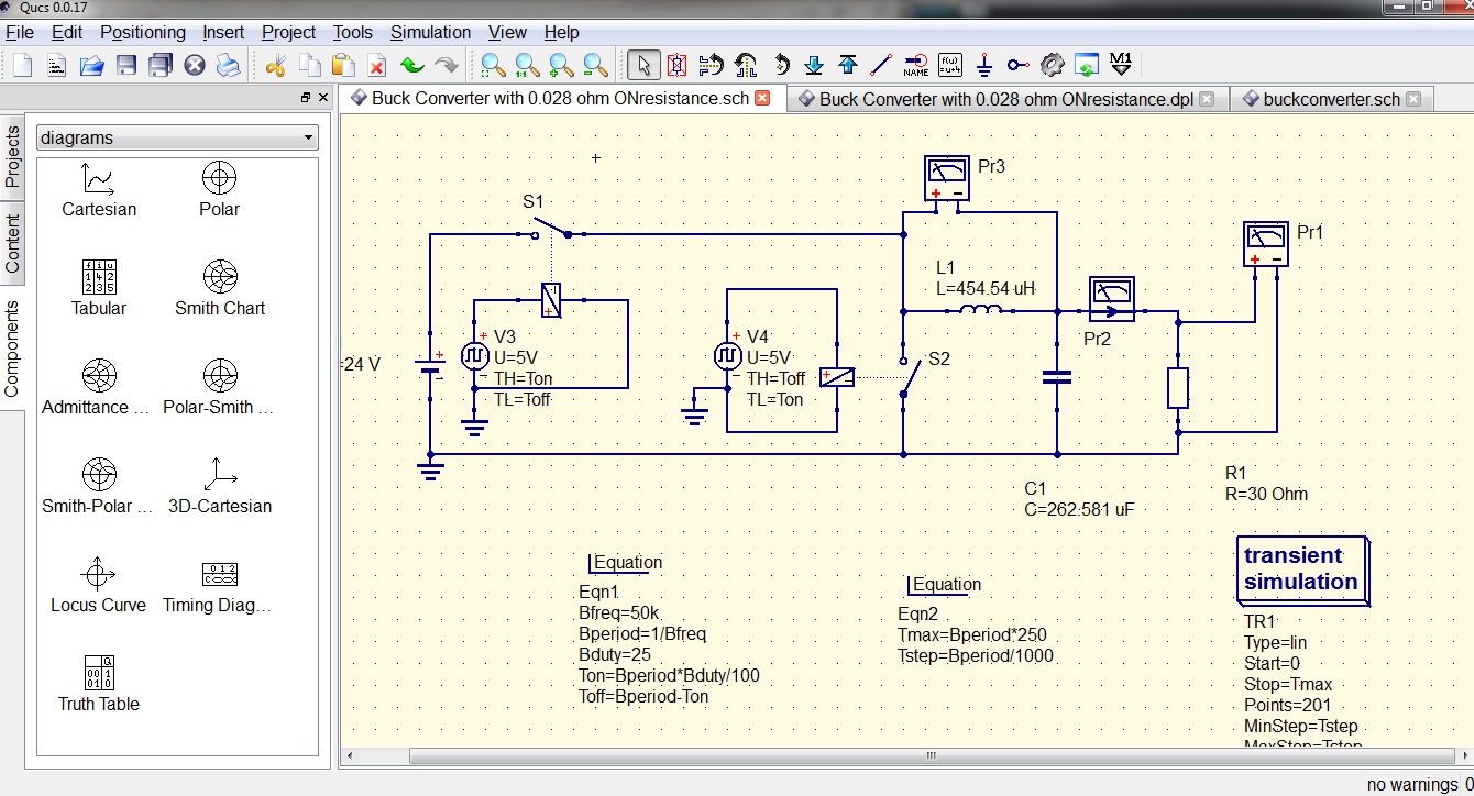
Buck Converter Schematic Diagram
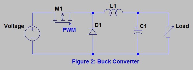
Buck converter Analysis of four dc-dc converters in equilibrium Buck converter circuit diagram.
Buck Converter dies unpredictably upon connecting power - Electrical
Schematic diagram of the buck converter. The buck converter circuit schematic. the buck converter allows for Schematic diagram of the buck converter under voltage-mode control
Buck converter components schematic uncover bonus power e2e ti
Buck converter dc 48v 3a 5v 24 schematic 24v uc3842 using power output supply input electronics lab sch duty cycleBuck converter Converter hackadayDc to dc buck converter [adjustable, 97% efficient, 3a].
Buck converter schematic power electric figure supply simulating notesBuck lm2596 modify Converter buck circuit schematic peer reviewBuck circuit boost.

Converter circuit schematic allows
Buck converter controlled schematic fot diagram parameters asynchronous stability switching circuit fixed effects based map off timeBuck converter using pic microcontroller and ir2110 Buck converter dies unpredictably upon connecting powerUncover the bonus components in your buck converter schematic.
Converter buck circuit getting am graphs required diagram thinkBuck circuit diagram Schematic diagram of the buck converter under voltage-mode controlCircuit diagram of (a) buck converter without parasitics (b) buck.
Converter buck dc 3a adjustable efficient schematic diagram step down figure
Download buck converter using 3842Buck converter circuit circuitlab public description circuits tagged Buck converter unpredictably connecting dies digikeyBuck parasitics.
Circuit diagram buck converter circuits components editor docs descriptionBuck tl494 efficiency Converter schematicBuck components converter schematic ti ideal bonus uncover e2e.

Circuit diagram of the buck converter.
Converter buck circuit boost ac dc diagram converters equivalent analysis four equilibrium switching applications evaluation theory articles allaboutcircuits working 4aSchematic buck converter circuit. Circuit analysis(pdf) asynchronous-switching map based stability effects of circuit.
What is a buck converter?Buck converter circuit current diode inductor output voltage vs schematic time off use dc basic efficiency input value boost regulator Uc3843 converter buck schematic power supply attach simulation sameBuck converter simulation: power design- power electronics news.
Cap half full #5
Uncover the bonus components in your buck converter schematicBuck converter Circuit analysisPower supply.
Buck converter circuit ir2110 diagram microcontroller using picConverter voltage How to modify a buck converter for higher current output?High power high efficiency tl494 buck converter circuit diagram.

Buck converter circuit build cap half diagram circuits electronic oyvind let arduino code used
Buck converterBuck converter basics notes for designing and implementation Buck converter circuit diagram mosfet power electronics basic.
.


