Cooling Tower Schematic Diagram
Schematic cooling tower system. source... What is a cooling tower? cooling tower basics Do you know what a forced draft cooling tower is?
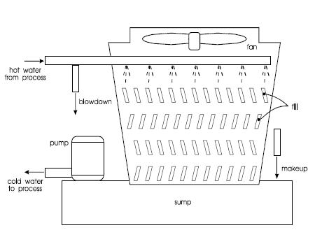
Schematic drawing showing the basic components of a cooling tower
Cooling towers explained: how does a cooling tower work Cooling tower flow diagram filtration filters water system filter stream side schematic systems towers basin document sand forsta replacements scope Tower schematic
Cooling towers information
Cooling tower parts counterflow towers diagram marley spx series connect diagram2Cooling tower towers work water working diagram principle system draft air forced used principles chemicals treatment evaporative types conditioning cooled Tower crossflow cooling diagram parts towers marley components pdf connect midwestCooling tower design companies.
Cooling towers explained: how does a cooling tower work(pdf) the effect of vortex generator on the approach value on forced Ac and cooling tower schematic diagramCooling tower diagram schematic ac dwg system detail cadbull description valve.

Cooling towers archives
Cooling componentsSchematic drawing showing the basic components of a cooling tower Thermal energies fillings crosswind experimentalCooling tower towers work does diagram draft induced mechanical explained engineeringclicks.
Cooling tower diagram hvac towers veris system iii series part systems workDraft counterflow airflow induced coolingtower Cooling tower schematic expansion systems diagram system towers evaporative fyiSchematic diagram of a counterflow cooling tower.

Towers nuclear draught condenser circulating turbine turbines employed mechanism
Schematic diagram of the cooling towerInduced draft counter flow cooling tower explained Cooling tower water makeup calculation schematic towers pump diagram system air recirculating information process efficiency selection heat counterflow building equipmentSchematic diagram of the cooling tower..
Cooling towers: hvac series part iiiCooling theconstructor Vortex draftWhat is a cooling tower?.
![counterflow-cooling-tower-diagram[2] - Midwest Cooling Towers](https://i2.wp.com/midwesttowers.com/wp-content/uploads/counterflow-cooling-tower-diagram2.png)
Cooling tower building diagram simplified
Expansion of cooling tower systemsCooling towers Mechanical engineering: schematic diagram of cooling towerCooling work towers tower draft induced diagram natural hyperbolic does water process labelled air they fan empty hot naturally system.
Cooling tower towers draft natural work diagram does explained engineeringclicksCooling tower diagram schematic mechanical engineering Cooling tower: cooling tower diagramCooling draft induced process encyclopedia.