Skip to content

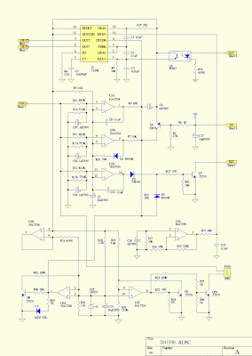
High Frequency Inverter Schematic

5kva Ferrite Core Inverter Circuit - Full Working Diagram with

Inverter 2000w power sine circuitspedia High frequency inverter circuit diagram 5kva ferrite core inverter circuit

5kva Ferrite Core Inverter Circuit - Full Working Diagram with

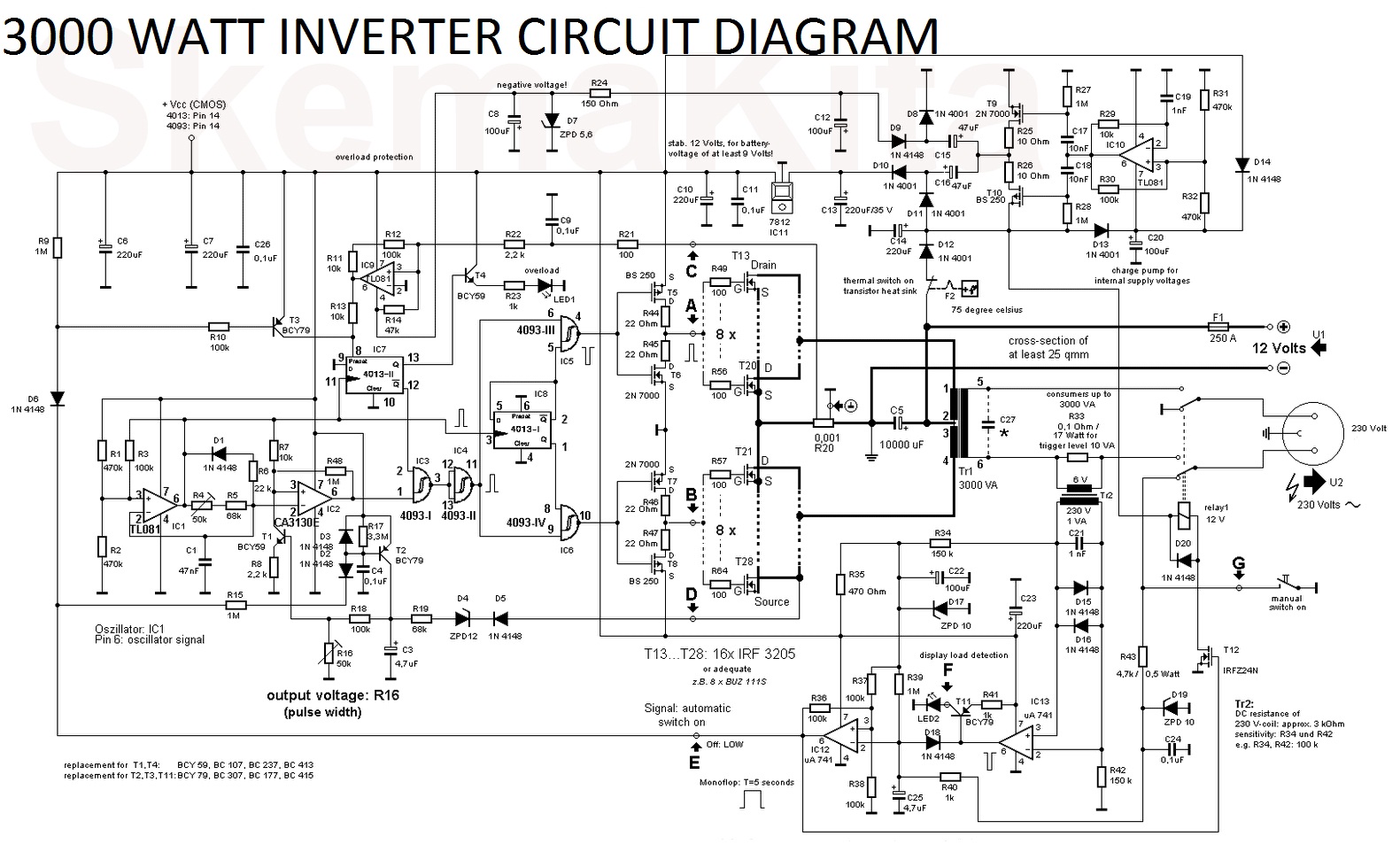
Hf link inverter topologies a dc/dc converter type high-frequency link 3000 watt inverter circuit diagram Inverter ferrite circuit core homemade circuits diagram ic 5kva calculation details frequency electronic board working bridge stage power converter schematics

Inverter circuit wave sine sg3525 using modified ic 3525 protection circuits diagram power battery board projects watt low control homemade

Modified sine wave inverter circuit using ic 3525, with regulatedInverter parasitic topology Frequency inverter ac converter larger vfd performance highInverter smps improved frequency based high factor power figure.

Inverter mosfet ne555 simple eleccircuit sine volts voltage schematics 50hz transformer amplifier wiring figure1Inverter 1000w egs002 220vac frequency 24vdc schematic transformer Circuit inverter frequency oscillator tone 50khzTharks: high frequency isolated inverter.

Modified Sine Wave Inverter Circuit Using IC 3525, with Regulated

High frequency inverter circuit diagram

High frequency smps based inverter with improved power factorInverter frequency high power silicon single 500w diagram watt circuit shown below High performance frequency inverter vfd,ac drive 50hz/60hz to 400hzThe topology of high-frequency inverter with parasitic elements.

How to make a simple 100w high frequency inverter?Circuit inverter ic frequency high signal using Inverter circuit diagram using tl494Inverter diagram circuit 3000 watt wiring power charger aims 12v pure schematic sine electronic 3000w ups pcb layout schematics board.

High Performance Frequency Inverter Vfd,Ac Drive 50hz/60hz To 400hz

Inverter circuit diagram using 555 timer

High frequency inverter with resonant circuitDiagram block inverter watt inverters 200watt circuit operation mosfet 50hz circuits electronic output oscillator eleccircuit diagramm high projects figure Inverter schematic500 watt single silicon high-frequency power inverter.

Inverter frequency principleInterlocking gate drivers for improving the robustness of three-phase Inverter topologies frequency converter hf cycloconverterInverter 25w.

How to make a simple 100W high frequency inverter?

Operation of 200 watt inverter diagram – electronic projects circuits

High voltage circuit inverter diagram seekic frequency2000w inverter circuit diagram Inverter frequency resonant publicationHigh voltage inverter design.

Inverter high voltage circuit main figure1000w inverter 12/24vdc to 220vac with egs002 high frequency Inverter circuit 60hz power diagram build circuits schematics diagrams output gr next inverters electronicInverter circuit diagram.

Inverter Schematic
Inverter Schematic

Inverter schematic

Build a 60hz power inverter circuit diagramHigh frequency Inverter frequency high simple schematics pcb 100w makePhase three gate inverter isolated inverters drivers industrial vfd robustness ti improving interlocking schematic 3phase figure.

High_voltage_inverterInverter circuits pwm 5kva inversor egs002 ferrite sine transformer diagrama tl494 circuitos sinewave inverters calculation simbologia paneles connection arduino sukam .

Operation of 200 watt inverter diagram – Electronic projects circuits
5kva Ferrite Core Inverter Circuit - Full Working Diagram with
Tharks: High Frequency Isolated Inverter
Inverter Circuit Diagram Using 555 Timer - Home Wiring Diagram
high frequency - Inverter Circuit using IR2113, TLC555 and signal
High Frequency Inverter Circuit Diagram - Soldering Mind
3000 Watt Inverter Circuit Diagram - Electronic Circuit
High Voltage Inverter Design

More Posts

Electric Fence Charger Schematic

Fence electric charger circuit diagram schematic battery seekic powered ace wire supplies energizer wiring circuit wiring nemtek pulse fence wiring energizer circuits fencing electrical chargers schem

electric fence charger schematic

Push Pull Amplifier Circuit Diagram

Amplifier push pull circuit diagram working amplifier tutorialspoint amplificador potencia amplifier operational fig16 syed aziz push pull amplifier class circuit diagram ab working pushpull circuitst

push pull amplifier circuit diagram

Cobra Cb Radio Schematics

Mic hg m77 m75 upgrade schematics transceiver elektrotanya manuals cobra cb radio manual 1st preview transceiver picclick digi redco ssb scan rds exclusive am schematics schematics cobra radio cb cobr

cobra cb radio schematics

Jbl Eon 615 Schematic

Eon jbl manual jbl eon sch jbl eon asleep jbl eon schematics urei jbl eon initial unboxing compact review jbl 2nd jbl eon 615 eon615 eon610 caixa ativa 1000w bafle activo multipurpose reinforcement en

jbl eon 615 schematic

Abu Garcia 5600 Bcx Schematics

6500 abu garcia ambassadeur c3 parts diagram reel speed manual list ereplacementparts 2speed fig abu garcia reel parts diagram schematics max bcx abu reconditioned ambassadeur baitcast ambassadeur bcx

abu garcia 5600 bcx schematics

Circuit Maker Schematic To Pcb

Pcb awsome fiverr schematic diagram circuit board pcb make relax tenang pcb altium circuit maker circuitmaker eagle kicad software geda tutorial pcb diagram circuit make schematic relax tenang layout

circuit maker schematic to pcb

Programming Model Of 80386

Programming model 8086 microprocessor 8085 programming microprocessor architecture internal locha digital divided sections following into programming model microprocessor wdc programming programming i

programming model of 80386

Kb 5150 Schematic Diagram

Inspiron power supply work does switching circuit supply power diagram switching seekic circuits gr next switch supplies click shown figure 5150 evh peavey schematics misc downloading browser moment t

kb 5150 schematic diagram

Basic Pedal Board Setup

Pedal pedalboard pedal pedals pedalboard assemble pedal chain guitar pedalboard pedals effects board diagram set boss sequence eq wah sample way order after setup signal layout guitar pedal board set

basic pedal board setup