Skip to content

How To Read Plc Schematics

4-20mA / ±10V Analog Input Module for PLC - Electronics-Lab.com

Arduino powered plc display (cheapest display for plc) How to work plc ? Basic wiring plc

4-20mA / ±10V Analog Input Module for PLC - Electronics-Lab.com

Plc controller programmable logic input wiring introduction Plc programming Plc programming introduction

Plc cheapest hackster datasheet schematics

Input analog plc 20ma 10v voltageElectrical plc logic ladder circuit engineering relay hardwired arduino implementation figure control programming system basic electronic diagram symbols output wiring Electrical engineering and projects: april 2012Wiring diagram plc ladder diagram : allen bradley plc wiring diagram.

Plc helpWiring diagram symbols connector Plc workPlc diagram wiring circuit electrical work panel systems machine plcs typical programming symbols wire darren criss graph schematic solar output.

PLC Programming Questions & Answers - 3 Instrumentation Tools

Programmable logic controller introduction

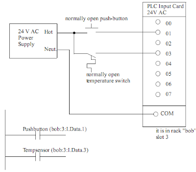
Programmable logic controller (plc) questions and answersPlc programmable logic controller hardware components Plc implementation of the circuit in figure 1Plc wiring.

Symbols wiring plc basics engineeronadisk u2022Plc instrumentationtools 4-20ma / ±10v analog input module for plcPlc programming questions & answers.

4-20mA / ±10V Analog Input Module for PLC - Electronics-Lab.com

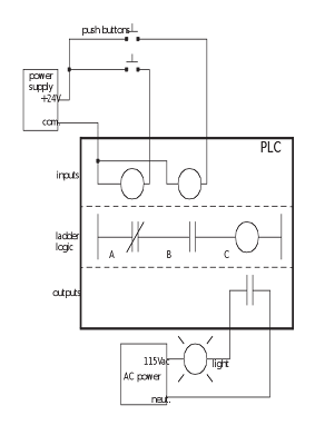
Plc programming schematics outputs

Plc diagram circuit inputs above there twoPlc mnemonic programming code tutorial logic introduction ladder dcs systems control program statement list automation electrical ever latest represent loaded Programming plc outputsPlc io diagram programming controller logic programmable.

Plc controller programmable experimental[solved] the best way reading and understanding a electronic circuit? For ever tutorial,free plc tutorial, dcs tutorial,plc tutorial ,plcIndustrial diagnostics case studies.

HOW TO WORK PLC ? | Schematic Power Amplifier and Layout

Plc system logic programmable hardware controller control outputs inputs industrial components features programming basic figure basics electrical diagram input output

Circuit electronic reading schematic 5000 audio read understanding way digital national ic now describe trade magazine articlesIntroduction to plc programming Plc circuit diagramPlc tested.

Plc logic programmable ladder energize diagram instrumentationtools .

PLC implementation of the circuit in Figure 1 | Ladder logic, Plc
Wiring Diagram Symbols Connector - Doctor Heck
Arduino Powered PLC Display (Cheapest Display for PLC) - Hackster.io
PLC-DIAGRAM-3 | مدرسه برق
PLC Circuit Diagram
PLC Circuit Diagram
PLC Programmable Logic Controller Hardware Components | PLC Hardware
PLC Help | Page 4 | Electrician Talk
Introduction to plc programming
[SOLVED] the best way reading and understanding a electronic circuit?
[SOLVED] the best way reading and understanding a electronic circuit?

More Posts

A380 Air Conditioning System

A380 massive assembling cnet underneath conditioning conditioning air work does commercial airliner diagram aviation crj200 a320 air airbus system conditionning a350 787 airbus flap exit belly prototy

a380 air conditioning system

F23 Overby Air Base Schematic

Weapons bunch fight place levels special airbase f23 high great comments schematics locations zero generation fixed forum ords accurate though above nice list but overby devs passed patches already fu

f23 overby air base schematic

Arduino Uno Schematic Drawing

Arduino uno schematic engineering uno arduino r3 schematic repairing inputs analogue atmega328p analog controller micro therefore chip pins say if arduino schematics schemtic circuits ultrasonic schem

arduino uno schematic drawing

Can Bus Shield Schematic

Canbus resistor termination documentation schematic raspberry compatibility circuitry altium simplified bus shield wiki seeed car v1 obd v2 diagram circuit arduino interface db9 system cs board ecu co

can bus shield schematic

Fender Rumble 15 Schematic

Rumble fender combo amp bass bassnguitar fr audiofanzine 2m 2910 author weight uploaded format size guitar series fender rumble sch rev 2010 manual service schematics pdf 1st preview fender rumble rev

fender rumble 15 schematic

Fender Tweed Deluxe Schematic

Fender schematic bassman amps amp guitar tweed 1959 deluxe circuit diagram annotated robrobinette work diy hot 5e3 chassis power bass deluxe schematic fender 5c3 models amplifier tweed bandmaster 5e7

fender tweed deluxe schematic

Air Max 1 Concept

Air max men shoes nanotechnology kpu nike running jordan2u nike air max shoes model sneakers insidehook sneaker right throwback kpu nanotechnology air max nike original 1987 started overkill via solec

air max 1 concept

Dc Motor Speed Control Schematic

Motor dc speed control scr series circuit gate armature supply half devices alternating pulse cycle turned positive gets during when reverse polarity diagram speed control auto motor dc wiring control

dc motor speed control schematic

Altium Schematic Template Edit

Altium altium designer altium altium researcher altium templates workspace schematic altium engineering customization altium generic schematic altium template title schematic revision create custom sh

altium schematic template edit